Executing an outdoor accessibility audit checklist requires measuring eight physical parameters on the ground with a 600 mm digital inclinometer, a rigid steel tape, and a 13 mm gap gauge: continuous clear width (>= 1,220 mm), running grade (<= 5.0%), cross-slope (<= 2.0%), curb ramp lip transitions (0 to 6.4 mm), surface caster indentation (<= 6.0 mm post-rain), transit drop-off proximity (<= 50 to 100 m), ADA portable toilet geometry (>= 1,525 mm turning circle), and a low-sensory recovery tent (< 45 to 50 dBA). Guessing route suitability from a satellite map or walking the park empty-handed fails manual wheelchair, rollator, and neurodivergent attendees midway through the event when a single un-ramped 20 mm tree-root lip, parallel storm-drain grate, or unmatted turf crossing blocks forward travel and prevents safe participation.
While our indoor and general accessibility checklist for a community event covers room entrances, 32-inch doorways, seated sightlines, and communication support, outdoor event accessibility introduces variable terrain, weather-softened substrates, cambered paths, and long transit approach distances. This guide translates U.S. Access Board Public Right-of-Way Accessibility Guidelines (PROWAG 36 CFR Part 1190), the 2010 ADA Standards for Accessible Design, U.S. Forest Service Outdoor Recreation Accessibility Guidelines (FSORAG / ABA Chapter 10), UK Department for Transport (DfT) Inclusive Mobility, and BSI PAS 6463:2022 into a field-reconnaissance protocol for Community Events and recurring walking groups.
| Audit Checkpoint | Field Measurement Instrument | Pass Threshold (Green: Score = 2) | Conditional Remediation (Amber: Score = 1) | Immediate Failure Trigger (Red: Score = 0) |
|---|---|---|---|---|
| 1. Clear Width and Passing Spaces | 5 m rigid steel tape + 30 m wheel |
>= 1,220 mm (48 in) continuous clear width (PROWAG R302.2); 1,525 × 1,525 mm (60 × 60 in) passing bay every <= 61 m (200 ft) |
915–1,219 mm (36–47.9 in) width with 815 mm (32 in) point pinch <= 610 mm (24 in) long (ADA Sec. 403.5) |
Any fixed pinch point < 815 mm (32 in), or path < 1,525 mm lacking passing bays for > 61 m |
| 2. Running Grade (Longitudinal Slope) | 600 mm (24 in) digital inclinometer |
<= 5.0% (1:20, or <= 30 mm rise per 600 mm level) continuous walkway without handrails |
5.1%–8.33% (1:12) ramp run <= 9.1 m (30 ft) or ABA 1017 trail <= 61 m with 1,525 mm level landings; disclose exact % |
Un-ramped grade > 8.33% on paved route, or natural trail segment > 12.5% (> 1:8) without step-free bypass |
| 3. Cross-Slope (Lateral Tilt) | 600 mm (24 in) digital inclinometer |
<= 2.0% (1:48, or <= 12 mm rise per 600 mm level) across paved paths and boardwalks |
2.1%–3.0% across compacted crushed stone trails for drainage (ABA 1017.3); warn manual chair users of lateral pull |
Paved cross-slope > 2.1% across driveway aprons, or natural trail cross-slope > 5.0% |
| 4. Curb Ramps, Lips, and DWS | Stepped wedge (6.4 / 13 mm) + tape |
0 mm flush gutter lip; vertical offsets <= 6.4 mm (0.25 in); counter-slope <= 5.0%; 610 mm (24 in) truncated domes |
6.4–13.0 mm (0.25–0.5 in) lip bridged with a <= 1:2 (50%) beveled threshold ramp before event start |
Un-beveled vertical lip > 6.4 mm, offset > 13 mm without ramp, or algebraic grade break > 13.33% |
| 5. Surface Firmness and Grate Slots | Loaded caster probe (100–135 kg) + 13 mm dowel |
Concrete, asphalt, boardwalk, or stabilized 1/4-in minus granite with < 6 mm sinkage; grate slots <= 13 mm perpendicular (90°) |
Soft grass verge < 100 m covered with pinned >= 1.22 m interlocking HDPE mats; parallel grates plated over |
Uncompacted pea gravel, woodchips, sand, or wet turf with > 12 mm caster sinkage; uncoverable > 13 mm parallel slots |
| 6. Transit Drop-Off and Rest Benches | 30 m (100 ft) measuring wheel + tape |
Paratransit drop-off (2.44 × 6.10 m + 1.52 m aisle) <= 50 m from hub; armrest benches (430–485 mm high) every <= 50–100 m |
Drop-off or ADA van bay at 51–100 m with a level midpoint bench at 50 m; bus stop at 101–200 m disclosed in invite |
Drop-off or parking > 100 m without rest seating, unramped curb at loading zone, or > 150 m between benches |
| 7. ADA Portable Restrooms | 5 m steel tape + spring scale / fist test |
>= 5% units (min 1 per cluster) on level pad; 1,525 × 1,525 mm exterior & interior turn space; >= 815 mm door (<= 22.2 N latch) |
Unit placed on grass bridged with pinned HDPE rollout mat and a <= 8.33% beveled threshold ramp |
Zero accessible toilets at a cluster, unit sited behind a curb or gravel, or latch requiring tight wrist pinching |
| 8. Quiet Sensory Tent and Signage | Class 2 dBA meter, lux meter + tape | PAS 6463 tent >= 30–50 m upwind of PA (< 45–50 dBA, < 150–200 lux); matte signs with C_LRV >= 70% and 25 mm text per 3 m |
Indoor quiet room <= 60 m away on step-free route; temporary high-contrast matte easel signs added at junctions |
No low-sensory space, quiet tent next to generator/PA (> 60 dBA), or low-contrast glossy laminated signage |
1. Field Measurement Kit and Sampling Cadence
Inclusive route planning starts two to four weeks before publishing an event invitation. Walking a park loop without measurement tools hides subtle barriers: the human eye routinely underestimates a 3.5% cross-slope or a 15 mm tree-root slab displacement that will stop a manual wheelchair or rollator cold.
Assemble a five-instrument reconnaissance kit before stepping onto the site:
600 mm(24 in) Digital Smart Level / Electronic Inclinometer: Calibrated to±0.1%accuracy to read longitudinal running grade (%) and perpendicular cross-slope (%). A600 mmrigid aluminum base bridges minor aggregate texture without tilted false readings from individual pebbles.5 m(16 ft) Rigid Steel Tape Measure (25 mmblade) +30 m(100 ft) Measuring Wheel: Measures unobstructed tread width between fixed pinch points,1,525 × 1,525 mm(60 × 60 in) passing bays, portable toilet interior turning circles, and cumulative walking distances from transit stops to rest benches.13 mm(0.5 in) Diameter Dowel Gauge + Stepped Lip Wedge (6.4 mmand13 mmsteps): Tests ADA Section 302.3 surface openings (storm drain grates, timber boardwalk plank seams, bridge expansion joints) and ADA Section 303 vertical changes in level.- Loaded Caster / Boot-Heel Indentation Probe (Field Proxy for ASTM F1951): Evaluates unpaved trail stability within
24 to 48 hoursafter rainfall by applying a100 to 135 kg(220 to 300 lb) vertical load onto a100 to 150 mm(4 to 6 in) front wheelchair caster (or pressing a25 mmsteel rod under150 Nforce with a180°twist) and measuring rut depth in millimeters. - Smartphone or Handheld Class 2 Sound Level Meter (
dBA) + Light Meter (lux): Measures continuous equivalent sound pressure (LAeqindBA) and ambient illuminance (lux) inside the quiet recovery tent while the main event PA speaker or generator runs at operating volume.
Digital Inclinometer Rise-to-Grade Conversion Math
When auditing with a 600 mm (24 in) level or checking a short ramp apron with a steel tape and spirit level, convert vertical rise (Rise_mm) over horizontal run (Run_mm) into percent grade (Grade%) using the linear slope formula:
Grade (%) = (Rise_mm / Run_mm) × 100
For a standard 600 mm (24 in) digital level base (Run_mm = 600), the exact vertical drop across the two ends of the level at each regulatory threshold is:
Rise_mm = (Grade% / 100) × 600
2.0%Cross-Slope Limit (PROWAG R302.5 / ADA Sec. 403.3):Rise_mm = (2.0 / 100) × 600 = 12.0 mm(0.47 invertical drop across the600 mmlevel).5.0%Walkway Running Grade Limit (PROWAG R302.4 / ADA Sec. 403.3):Rise_mm = (5.0 / 100) × 600 = 30.0 mm(1.18 inrise across the600 mmlevel).8.33%Maximum Curb Ramp Grade (PROWAG R304.2.2 / ADA Sec. 405.2):Rise_mm = (8.33 / 100) × 600 = 50.0 mm(1.97 inrise across the600 mmlevel).
Sample running grade and cross-slope every 15 to 30 meters (50 to 100 feet) along uniform paved segments, and measure 100% of curb ramps, driveway crossings, bridge approaches, tree-root heaves, and drainage swales.
Takeaway: Carry a 600 mm digital level, a 13 mm dowel gauge, a steel tape, and a measuring wheel on every pre-event reconnaissance walk; sample uniform paths every 15 to 30 m and inspect 100% of curb transitions and grates.
2. Route Geometry, Slopes, and Curb Ramp Tolerances (PROWAG R302/R304 and ABA 1017)
For foundational route concepts, see how to organise an inclusive walk; for pace cohort timing and volunteer back-marker ratios on recurring group walks, see how to start a walking club. When auditing an outdoor community event venue or park trail, apply the dimensional tolerances codified in PROWAG Sections R302, R304, and R305, 2010 ADA Standards Sections 303, 403, 405, and 406, and ABA Chapter 10 (Section 1017 Trails) / USFS FSORAG.
Clear Width, Pinch Points, Passing Spaces, and Headroom
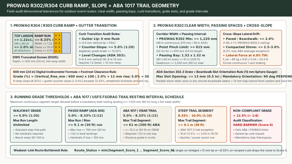
- Continuous clear width: PROWAG R302.2 mandates a minimum unobstructed pedestrian access route width of
>= 1,220 mm(48 in), while UK DfT Inclusive Mobility recommends1,525 mm(60 in) for a wheelchair user and walking companion to travel side-by-side (1,800 to 2,000 mmfor two wheelchairs to pass comfortably). Under older on-site ADA Section 403.5.1 rules, clear width must never drop below915 mm(36 in), narrowing to815 mm(32 in) only at isolated point obstacles (such as a bollard or gate post) for a maximum length of610 mm(24 in). - Passing space intervals: Whenever continuous path width is less than
1,525 mm(60 in), verify a level1,525 × 1,525 mm(60 × 60 in) passing bay at intervals not exceeding61 m(200 ft) under PROWAG R302.4 and ADA Section 403.5.3 (<= 50 munder UK DfT Inclusive Mobility). - Overhead vertical clearance: Confirm
>= 2,030 mm(80 in) continuous vertical headroom across the full width of the path (ADA Section 307.4 / PROWAG R402.4;2,100 to 2,300 mmunder UK guidelines). Prune rain-weighted overhanging branches and check marquee valances or guy-lines.
Running Grade Limits and ABA 1017 Trail Resting Intervals
Any continuous walkway segment with a running slope <= 5.0% (1:20) is permitted for unlimited distance without handrails or ramp landings. Paved segments exceeding 5.0% up to 8.33% (1:12) are legally ramps under ADA Section 405: they cannot exceed 9.1 m (30 ft) in horizontal run or 760 mm (30 in) in vertical rise before a mandatory 1,525 mm (60 in) level landing (<= 2.0%), and they require handrails (865 to 965 mm / 34 to 38 in high) plus edge protection whenever the rise exceeds 150 mm (6 in).
On unpaved park and forest trails governed by ABA Section 1017.2 and USFS FSORAG, steeper natural grades are permitted only over strict maximum segment lengths separated by level resting intervals (>= 1,525 mm [60 in] long, at least as wide as the widest trail segment leading to it, with slope <= 2.0% on paved Pads or <= 5.0% for natural drainage):
0.0% to 5.0%(<= 1:20): Any segment length permitted without mandatory trail resting intervals.5.0% to 8.33%(1:20to1:12): Maximum segment length<= 61 m(200 ft) on ABA trails (<= 15.2 m[50 ft] on FSORAG Outdoor Recreation Access Routes [ORAR]) between1,525 mmresting intervals.8.33% to 10.0%(1:12to1:10): Maximum segment length<= 9.1 m(30 ft) between1,525 mmresting intervals.10.0% to 12.5%(1:10to1:8): Maximum segment length<= 3.05 m(10 ft) between1,525 mmresting intervals. Flag any segment above8.33%in your pre-event access notice because manual wheelchair users often require power-assist or a spotter on slopes above1:12.> 12.5%(> 1:8): Fails accessible trail standards (Score = 0); establish a step-free bypass or relocate the route.
Cross-Slope Biomechanics and Lateral Caster Drift Calculation
Why is cross-slope capped at <= 2.0% (1:48) on paved paths and boardwalks? Because manual wheelchairs rely on low-friction swiveling front casters, any lateral tilt across the path generates a continuous downhill gravitational force vector (F_lateral) perpendicular to travel:
F_lateral = m × g × sin(arctan(Cross_Slope / 100))
Where:
m= Combined mass of the participant and wheelchair in kilograms.g= Gravitational acceleration (9.81 m/s²).Cross_Slope= Perpendicular slope in percent (%).
Worked Biomechanical Example:
Consider a manual wheelchair user with a combined rider-and-chair mass of m = 85 kg traversing a cambered park asphalt path or driveway apron with a 4.0% cross-slope (double the 2.0% ADA limit):
arctan(4.0 / 100) = arctan(0.04) = 2.2906 degreessin(2.2906 degrees) = 0.03997F_lateral = 85 × 9.81 × 0.03997 = 33.33 N(7.49 lbf) of continuous sideways drag pulling the front casters toward the downhill verge.
To keep from veering off the path, the rider must brake on the uphill push-rim while propelling almost exclusively with the downhill arm, doubling unilateral shoulder and wrist torque and causing severe upper-limb fatigue within 150 to 300 meters (for details on manual and power wheelchair metabolic energy expenditure, see inclusive corporate wellness challenge design). On natural compacted aggregate trails where surface water drainage is required, keep operational cross-slope <= 2.5% to 3.0% (never exceeding the 5.0% ABA 1017.3 absolute ceiling).
Curb Ramps, Algebraic Grade Break, and Detectable Warnings (PROWAG R304/R305)
At every street crossing or parking lot transition along the event route, verify six curb ramp checkpoints:
- Ramp run width and slope: Clear width
>= 1,220 mm(48 in) under PROWAG R304.5.1 (>= 915 mm[36 in] under older on-site ADA Section 406.1, excluding flares), running slope<= 8.33%(1:12), and side flares<= 10.0%(1:10). - Top turning landing: At least
1,220 × 1,220 mm(48 × 48 in) at the top of perpendicular curb ramps with slope<= 2.0%in all directions so a wheelchair user can turn onto the sidewalk without tipping back toward traffic. - Flush lip and vertical offsets (ADA Sec. 303): The transition between the curb ramp and street gutter must be flush (
0 mmlip). Along the general walkway, vertical changes<= 6.4 mm(0.25 in) may be vertical; offsets between6.4 mmand13 mm(0.25 to 0.5 in) require a<= 1:2(50%) bevel; offsets> 13 mm(0.5 in) require a ramp (<= 8.33%). - Gutter counter-slope and algebraic grade break: Street gutter counter-slope must not exceed
5.0%(1:20), keeping the algebraic grade break (Ramp_Grade% + Gutter_Counter_Slope%) at or below13.33%. An algebraic grade break above13.33%bottoms out wheelchair footrests and rear anti-tip wheels. - Detectable Warning Surfaces (DWS, PROWAG R305 / ADA Sec. 705): Confirm a
610 mm(24 in) deep strip of truncated domes extending across the full width of the curb ramp or blended transition, with dome rows aligned parallel to wheel travel and strong visual contrast against the surrounding concrete.
Takeaway: Enforce <= 5.0% running grade, <= 2.0% cross-slope, 0 mm curb lips, and <= 13.33% algebraic grade breaks across every curb transition; any single un-beveled lip over 6.4 mm or un-ramped offset over 13 mm requires a temporary threshold ramp or route bypass.
3. Surface Firmness, Caster Sinkage, and Grate Orientation (ASTM F1951 and ADA 302)
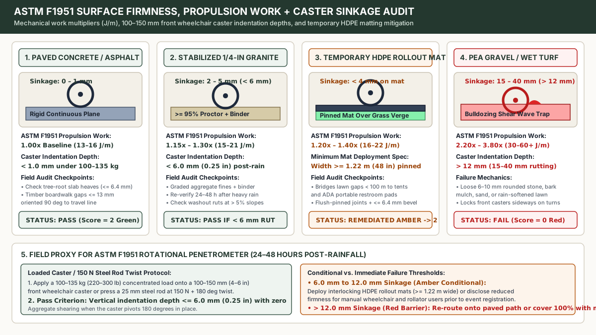
Park descriptions frequently label gravel paths or grass lawns as “flat and wheelchair accessible.” Under ADA Section 302.1 and PROWAG R302.6, ground surfaces must be stable, firm, and slip-resistant. The laboratory benchmark governing exterior surface accessibility is ASTM F1951 (Standard Specification for Determination of Accessibility of Surface Systems), which measures the mechanical work in Newton-meters per meter (J/m) required to propel a test wheelchair across a level and 7.1% (1:14) sloped surface compared to a smooth rigid reference plane.
Why Uncompacted Pea Gravel and Wet Turf Fail ASTM F1951
- Paved Concrete, Smooth Asphalt, and Timber Boardwalks (
1.00×Baseline Work,< 1 mmSinkage): Require13 to 16 J/mof mechanical propulsion work on level ground. Front wheelchair casters (100 to 150 mmdiameter,25 to 38 mmwidth) roll with minimal rolling resistance. - Stabilized
1/4-Inch MinusCrushed Granite or Limestone Fines (1.15× to 1.30×Work,< 6 mmSinkage): Graded angular stone screenings (<= 6.4 mmdown to dust) mixed with an organic or polymer binder and compacted to>= 95%Standard Proctor density pass ASTM F1951 when vertical caster indentation stays below6.0 mm(0.25 in) even24 to 48 hoursafter rain. - Uncompacted Pea Gravel, Bark Mulch, Sand, and Rain-Saturated Turf (
2.20× to 3.80×Work,15 to 40 mmSinkage): Rounded pea gravel (6 to 10 mmstone without fines), woodchips, and wet lawn lack shear cohesion. Under a100 to 135 kguser-and-chair load, narrow front casters and rollator wheels sink15 to 40 mm(> 12 mmfailure threshold), pushing a continuous bulldozing wave of stone or mud ahead of the wheel, locking casters sideways during turns, and causing cane or crutch tips to punch down into the substrate.
Temporary Event Matting and Grate Slot Orientation (ADA 302.3)
When an outdoor event hub requires crossing a grass verge for < 100 m to reach a marquee, registration desk, or portable toilet cluster, lay interlocking heavy-duty HDPE or composite pedestrian rollout mats (>= 1,220 mm [48 in] wide, pinned flush to the ground with <= 6.4 mm beveled edge transitions).
Simultaneously, test every storm drain grate, trench drain, cattle grid, and timber boardwalk seam along the loop with your 13 mm (0.5 in) dowel gauge:
- Maximum opening: Surface gaps must not allow passage of a
13 mm(0.5 in) sphere (ADA Section 302.3 / PROWAG R302.6.2). Because timber boardwalk planks shrink during dry summer weeks, a seam constructed at10 mmin winter can widen to16 to 19 mmin August. - Perpendicular slot orientation: Elongated grate bars and boardwalk plank joints must run strictly perpendicular (
90°) to the dominant direction of travel so narrow wheelchair casters and cane ferrules roll across the bars rather than dropping parallel into the slot. Cover any parallel-slotted grate or> 13 mmgap with a bolted non-slip steel plate or beveled rubber threshold mat before the event opens.
Takeaway: Reject loose pea gravel, woodchips, and unmatted turf (> 12 mm caster sinkage); require paved surfaces, compacted 1/4-in minus stabilized stone (< 6 mm indentation), or >= 1.22 m HDPE rollout mats, and plate over any grate slot wider than 13 mm or aligned parallel to travel.
4. Event Hub Zoning: Transit Drop-Off, ADA Restrooms, PAS 6463 Quiet Tent, and Wayfinding
An outdoor route audit extends beyond the walking trail to the arrival interchange, toilet facilities, sensory recovery space, and directional signs. Research summarized in UK DfT Inclusive Mobility demonstrates that roughly 75% of disabled pedestrians using walking sticks or crutches and 60% of older mobility-impaired walkers cannot cover more than 50 to 100 meters without a rest pause.
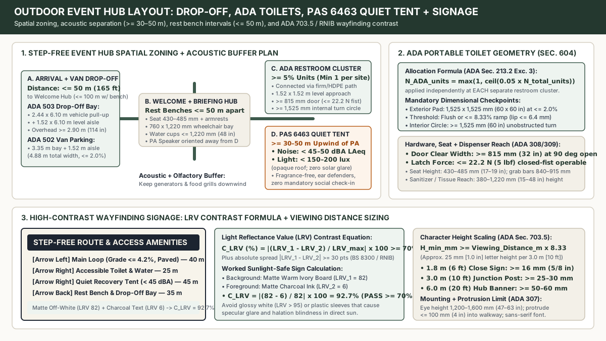
Transit, Paratransit Drop-Off, and Van Parking Proximity (ADA 502/503)
- Passenger loading / paratransit drop-off bay (ADA Sec. 503): Locate a step-free drop-off zone within
<= 50 m(165 ft) of the welcome hub (<= 60 mDfT Inclusive Mobility ceiling without seating). The bay requires a>= 2,440 mm(96 in) wide by6,100 mm(20 ft) long pull-up space plus an adjacent parallel access aisle>= 1,525 mm(60 in) wide by6,100 mm(20 ft) long at<= 2.0%slope, connected to the path by a flush curb ramp, with>= 2,895 mm(114 in/9 ft 6 in) overhead clearance for high-roof paratransit vans. - Van-accessible parking bays (ADA Sec. 502): Locate Blue Badge / ADA van bays within
<= 50 to 100 m(165 to 330 ft) of the hub (placing a level armrest bench at the50 mmidpoint if distance exceeds50 m). Each van space requires a combined bay-plus-aisle width of4,880 mm(192 in/16 ft: either a3,350 mm[11 ft] vehicle bay +1,525 mm[5 ft] access aisle, or a2,440 mm[8 ft] bay +2,440 mm[8 ft] aisle) sloped at<= 2.0%so side-entry hydraulic lifts can deploy cleanly onto firm pavement. - Public transit stop disclosure: Ideal bus or rail stop distance is
<= 200 m(650 ft), with an absolute outer ceiling of<= 400 m(0.25 mi) only when connected by continuous paved sidewalks with curb ramps and rest benches every100 m. Always publish the exact measured distance in meters and yards in the pre-event invitation. - Rest bench intervals and ergonomics (ADA Sec. 903 / DfT Sec. 3.8): Provide benches every
<= 50 m(165 ft) inside the event hub and every<= 100 to 150 m(330 to 500 ft) along outer walking loops. Each bench requires a seat height of430 to 485 mm(17 to 19 in), seat depth of510 to 610 mm(20 to 24 in), full backrest, sturdy dual armrests for sit-to-stand push-off, and an adjacent760 × 1,220 mm(30 × 48 in) level firm companion bay for a wheelchair or rollator.
Accessible Portable Restroom Allocation and Geometry (ADA 213.2 and 604)
Under 2010 ADA Standards Section 213.2 Exception 3 and the ADA National Network Temporary Events Guide, calculate the required number of wheelchair-accessible portable toilets at each separate restroom cluster using the ceiling allocation formula:
N_ADA_toilets = max(1, ceil(0.05 × N_total_cluster))
If you place 1 standalone portable unit at a remote trailhead and 14 portable units at the main festival hub, the trailhead requires max(1, ceil(0.05 × 1)) = 1 accessible unit and the main hub requires max(1, ceil(0.05 × 14)) = max(1, ceil(0.70)) = 1 accessible unit (or 2 accessible units if the main cluster has 21 to 40 total units). Every accessible portable toilet must pass five physical checks:
- Placed on a firm, level (
<= 2.0%) paved pad or HDPE mat directly adjoining the step-free route (never lifted onto a curb or set behind unpaved grass). - Unobstructed
1,525 × 1,525 mm(60 × 60 in) level exterior maneuvering clearance in front of the door so a user pulling the door open does not roll backward down a slope. - Threshold flush or ramped at
<= 8.33%(1:12) with a beveled edge<= 6.4 mm(0.25 in). - Door clear opening
>= 815 mm(32 in) at90°open, fitted with a loop or lever latch operable with a closed fist using<= 22.2 N(5 lbf) force and zero tight pinching or wrist twisting (ADA Section 309.4). - Unobstructed
>= 1,525 mm(60 in) diameter internal turning circle, seat height430 to 485 mm(17 to 19 in), horizontal and vertical grab bars (840 to 915 mm[33 to 36 in] high), and sanitizer/tissue dispensers mounted within380 to 1,220 mm(15 to 48 in) reach height.
PAS 6463 Quiet Sensory Recovery Tent Engineering
Outdoor community events often combine amplified PA announcements, crowd chatter, food generator hum, and bright overhead sun. Grounded in BSI PAS 6463:2022 (Design for the mind: Neurodiversity and the built environment) and the indoor low-sensory parameters in our low-barrier workplace wellness ideas guide, set up a dedicated Quiet Sensory Recovery Tent (or step-free indoor quiet room):
- Spatial and acoustic separation: Site the tent
>= 30 to 50 m(100 to 165 ft) upwind and acoustically shielded from PA speakers, buskers, diesel/petrol generators, and catering queues. Confirm with your Class 2 sound meter that internal ambient sound stays< 45 to 50 dBAwhen the main PA is active. - Visual and solar glare control: Use an opaque-lined marquee roof or shaded canopy so internal illuminance stays
< 150 to 200 lux. Avoid unlined translucent white PVC tent roofs, which act as giant solar diffusers exceeding3,000 to 5,000 luxand triggering migraine or sensory overload. - Thermal, olfactory, and autonomy rules: Keep the tent strictly fragrance-free and upwind of food grills. When outdoor temperatures exceed
26.7°C(80°F) or drop below10°C(50°F), provide shaded cooling/water or wind-sheltered warmth per the ADA Temporary Events Guide. Stock armrest chairs, a1,525 mmwheelchair space, water cups at<= 1,220 mm(48 in) reach height, and disposable foam earplugs. Frame entry, rest pauses, and early departure as ordinary choices requiring zero sign-in or explanation.
High-Contrast Wayfinding Signage: LRV Contrast and Viewing Distance Math
Temporary event signs printed on pastel card or slipped into glossy plastic sleeves become unreadable in outdoor glare. Under 2010 ADA Standards Section 703.5, BS 8300, and RNIB Clear Print Guidelines, audit every directional and access sign using two equations:
1. Light Reflectance Value (LRV) Contrast Equation
C_LRV (%) = |(LRV_background - LRV_foreground) / max(LRV_background, LRV_foreground)| × 100 >= 70%
In addition to C_LRV >= 70%, maintain an absolute reflectance spread of |LRV_background - LRV_foreground| >= 30 points.
- Worked Sunlight-Safe Sign Example: Printing matte charcoal text (
LRV_foreground = 6) on a matte warm ivory/off-white signboard (LRV_background = 82) yields:C_LRV = |(82 - 6) / 82| × 100 = (76 / 82) × 100 = 92.7%(Passes>= 70%, with a76-pointLRV spread). Using warm off-white (LRV 80–85) with a matte finish eliminates the blinding specular halation caused by glossy pure white board (LRV > 95) or laminated plastic sleeves in direct sun.
2. Minimum Character Height by Viewing Distance
H_min_mm = Viewing_Distance_m × 8.33 (or 25 mm [1.0 in] uppercase letter height per 3.0 m [10 ft] of viewing distance, above the 16 mm [5/8 in] ADA baseline for < 1.8 m viewing):
- Close route map / clipboard at
1.8 m(6 ft):H_min_mm >= 16 mm(5/8 in). - Trail junction directional post viewed from
3.0 m(10 ft):H_min_mm = 3.0 × 8.33 = 25.0 mm(1.0 in; use25 to 30 mmsans-serif type such as Atkinson Hyperlegible, Helvetica, or Transport). - Main hub banner (Toilets / Quiet Tent / Drop-Off) viewed from
6.0 m(20 ft):H_min_mm = 6.0 × 8.33 = 50.0 mm(2.0 in; use50 to 60 mmlettering).
Mount signs at 1,200 to 1,600 mm (47 to 63 in) eye height alongside the path, ensuring no sign frame or A-board protrudes more than 100 mm (4 in) into the clear walkway width (ADA Section 307.2).
Takeaway: Site paratransit drop-offs within <= 50 m, allocate >= 5% (min 1) ADA portable toilets per cluster on firm level pads, buffer the PAS 6463 quiet tent >= 30 to 50 m from PA speakers (< 45 to 50 dBA), and print matte wayfinding signs with C_LRV >= 70% and 25 mm letters per 3 m viewing distance.
5. Weakest-Link Route Scoring and Pre-Event Access Disclosure
An outdoor route functions as a serial chain of N segments: Arrival Drop-Off (Segment 1) -> Curb Ramp Transition (Segment 2) -> Welcome Hub (Segment 3) -> Main Loop Segments (Segments 4..k) -> Restroom Approach (Segment N-1) -> Quiet Recovery Tent (Segment N). Because a single unramped 100 mm curb or a 20 m stretch of unmatted turf blocks a wheelchair user from reaching the toilet or completing the loop, overall route accessibility follows the Weakest-Link Bottleneck Rule rather than an average score:
Route_Status = min(Segment_Score_1, Segment_Score_2, ..., Segment_Score_N)
Where each segment is scored during reconnaissance as:
Score = 2(Green / Pass): Meets all PROWAG R302/R304, ADA, ASTM F1951, and PAS 6463 pass thresholds natively.Score = 1(Amber / Conditional): Contains a remediable defect (such as a10 mmlip, a20 mturf crossing to portable toilets, or a parallel storm grate) that can be upgraded toScore = 2via temporary field hardware before event day, or a natural trail grade (5.1% to 8.33%with resting intervals) that requires explicit numerical pre-disclosure.Score = 0(Red / Hard Barrier): Contains an un-remediated barrier (such as steps, a pinch point< 815 mm, loose pea gravel> 12 mmsinkage, or grade> 12.5%).
Track your pre-event remediation progress using the Segment Audit Compliance Rate (ACR%):
ACR (%) = ((N_green_segments + N_remediated_amber_segments) / N_total_critical_checkpoints) × 100
Worked 6-Zone Park Audit and Remediation Calculation
Suppose an organiser audits 6 sequential zones for a Saturday community park event:
- Zone 1 (Paratransit Drop-Off):
35 mfrom hub,1.5%slope, flush curb ramp ->Score = 2(Green). - Zone 2 (Park Entrance Curb Cut):
1,250 mmwide,7.2%slope,0 mmlip,610 mmtruncated domes ->Score = 2(Green). - Zone 3 (Main Paved Loop):
1,800 mmasphalt width,3.2%max running grade,1.5%cross-slope, armrest benches every110 m->Score = 2(Green). - Zone 4 (Culvert Storm Grate):
19 mmslots oriented parallel to travel -> InitialScore = 0(Red Barrier). - Zone 5 (Portable Restroom Approach):
1ADA toilet unit (1,525 mmturn space) placed22 macross soft grass lawn (18 mmcaster sinkage) -> InitialScore = 0(Red Barrier). - Zone 6 (PAS 6463 Quiet Tent): Shaded opaque tent
45 mupwind of PA speaker,43 dBAinternal sound,140 lux->Score = 2(Green).
Before remediation, Route_Status = min(2, 2, 2, 0, 0, 2) = 0 (Blocked), and ACR% = (4 / 6) × 100 = 66.7%. Two days before the event, the team bolts a 6 mm beveled non-slip steel cover plate over the Zone 4 grate (Score 0 -> 2) and pins 25 m of 1.22 m wide interlocking HDPE rollout matting across the Zone 5 lawn to the ADA portable toilet pad (Score 0 -> 2). Post-remediation Route_Status = min(2, 2, 2, 2, 2, 2) = 2, raising ACR% to (6 / 6) × 100 = 100%.
Date-Stamped Pre-Event Access Disclosure Template
Publish the measured numbers directly on the event page so attendees never have to email or phone to ask whether they can attend. Follow the person-first phrasing principles in respectful language for mental health conversations and the 5-field verification standard (facility, coverage, specific measurements, source/method, and last-checked date) in how to keep a community support directory reliable:
- Audit Date and Weather Condition: State the exact date the route was measured and whether unpaved segments were checked after rain (for example: Route measured on 24 October 2026 using a 600 mm digital level and steel tape, 36 hours after rainfall).
- Arrival and Transit Distances: State the exact distance in meters and yards from the nearest step-free bus/rail stop (
140 m / 153 yd) and the on-site accessible drop-off bay (35 m / 38 ydfrom the welcome table). - Corridor Width, Surface, and Maximum Grade: State the narrowest clear width (
1.45 m / 57 inat the west gate), surface type (smooth tarmac plus 25 m of pinned HDPE rollout matting to the toilets), maximum running grade (4.2%for18 mat the pond bridge), and maximum cross-slope (1.8%). - Rest Seating, Accessible Toilets, and Quiet Space: List bench spacing (
armrest benches with wheelchair companion bays every 90 to 120 m), toilet geometry (1 wheelchair-accessible unit with a 1,525 mm turning circle and closed-fist latch at the start hub, plus drinking water cups at 1,100 mm height), and sensory recovery details (shaded Quiet Recovery Tent 45 m north of the welcome table, < 45 dBA, no check-in required). - Ordinary Pauses and Early Departure: State explicitly that anyone may rest at any bench, take the
400 mstep-free shortcut, or leave at any time without giving a reason.
Takeaway: Score your route using the Weakest-Link Bottleneck formula (Route_Status = min(Segment_Score_i)), remediate every Score 0/1 barrier with temporary ramps, grate plates, or HDPE mats before event day, and publish a date-stamped numerical access block on the invitation.